New product launches in the plastics manufacturing world are often derailed by one sobering reality: the vast majority of injection mold designs fail initial trials. In fact, industry analyses reveal that most defects in injection molding don’t come from the production line at all, but originate in the product’s initial design stages. In other words, up to ~80% of mold problems are “designed in” before a single shot is molded. For something as commonplace as a computer mouse – which typically consists of multiple precision plastic parts (upper and lower housings, button mechanisms, etc.) – these early design mistakes can spell disaster.

Common Injection Mold Design Failures and Consequences
| Failure Type | Typical Consequences | Preventive Measures |
|---|---|---|
| Poor Material Selection | Cracks, warpage, or stress cracking | Match resin to specs, test for shrinkage, use PC-ABS or reinforced plastics |
| Insufficient Draft Angle | Parts stick in mold, scuffed surfaces | Apply 1°–3° draft, simulate ejection during CAD modeling |
| Button Misalignment | Inconsistent or failed button clicks | Tolerance analysis, include alignment pins |
| Tooling Inaccuracies | Flash, part mismatch, short tool life | Use hardened steel (e.g. H13), precision calibration |
| Prototyping Gaps | User discomfort, performance issues not caught early | Build and test fully functional prototypes |
| Testing Gaps | Failed quality inspections, costly post-launch fixes | Include pilot runs, life cycle testing, DFM validation |
When a mold design fails, the consequences hit fast and hard. The project faces T1 trial failures, repeated mold modifications, delayed launches, and unexpected costs. A General Motors case study is telling: by ignoring a mold-flow warpage warning during design, the team had to spend over $100,000 and 43 extra days to fix wall thickness issues after the steel mold was already cut. Conversely, another team that proactively tweaked the design (relocating a gate to eliminate a weak weld line) reportedly saved $1.1 million in potential fixes. The lesson is clear – catching and correcting issues in the design phase is orders of magnitude cheaper and faster than after tooling is built. Most injection molding failures share one thing in common: they’re caught too late, when a flaw found during first article inspection demands expensive tool rework.
Why are mouse mold designs in particular so prone to failure? A computer mouse might seem like a simple device, but its plastic parts must meet tight ergonomic, aesthetic, and functional requirements. The top shell with built-in buttons must precisely align with internal switches; the scroll wheel, side buttons, and bottom cover all need to fit and function without binding. Achieving this requires near-perfect design for manufacturability. Unfortunately, product designers (and even some toolmakers) can underestimate the complexities of injection molding. They may design in CAD under ideal conditions that don’t reflect real-world manufacturing tolerances, material behaviors, or assembly realities. The result? Around 4 out of 5 designs require significant revision before they can reliably churn out good parts. In the sections below, we’ll explore the common failure causes and how to avoid them.
1. Poor Material Selection – The Wrong Plastic for the Job
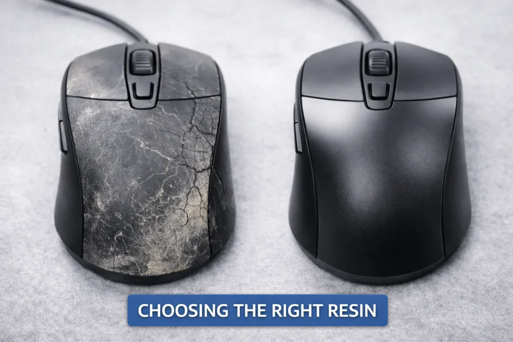
One of the costliest design mistakes is selecting a plastic resin that isn’t well-suited for the product’s requirements or manufacturing process. It’s easy to see how this happens: a designer might choose a material based on a datasheet property (e.g. high strength or a glossy finish) without realizing the material’s real-world molding behavior will differ. A resin data sheet provides properties measured on ideal laboratory test specimens, but actual molded parts often underperform those specs due to processing effects. For example, a polymer’s listed impact strength might assume perfectly dried material and no additives, whereas in production the resin could have slight moisture or colorant that makes parts more brittle. Fiber-filled plastics can warp or have anisotropic strength because fibers align with flow, yielding uneven stiffness across the part. If these nuances aren’t accounted for, the chosen material may lead to cracks, warping, or premature failure in use.
Importantly, material selection isn’t just about strength or appearance – it’s about the end-use environment. Plastics can be sensitive to temperature extremes, UV exposure, or chemicals. Choosing a resin without considering these factors can doom a product. Industry data shows that environmental stress cracking (ESC) – where plastic parts crack due to chemical exposure or stress – accounts for roughly 25% of plastic component failures. Imagine specifying an ABS plastic for a mouse housing for its toughness, only to discover that skin oils or a cleaning solvent cause the ABS to craze and crack over time. (Indeed, there are documented cases of ABS parts cracking from chemical interactions, and polycarbonate parts failing after exposure to alcohol-based cleaners.) Using a material outside its comfort zone can result in high warranty claims or field failures, forcing a late redesign. If you switch materials after the mold is built, the different shrinkage rate might mean the entire tool has to be re-machined – a nightmare scenario for an OEM.
Good DFM practice requires matching the plastic to the product’s needs and designing the mold around that material’s characteristics. Key considerations include the resin’s strength, rigidity, heat resistance (will the mouse see high temperatures in use or shipping?), shrinkage rate (critical for part dimensions and assembly fit), and any regulatory requirements (e.g. UL flammability, RoHS compliance). Cost should not be the sole driver. Selecting the cheapest resin without evaluating performance in context is a recipe for trouble. For instance, a material that’s too stiff might make thin hinge features (like battery door latches) prone to snapping, whereas a more flexible resin could survive. On the other hand, a material that’s not stiff enough might cause the assembled mouse to feel flimsy or allow excessive wear on button posts. There’s also the question of process compatibility: if the mouse has any overmolded rubber grips or two-shot components, the materials must bond or at least not interfere with each other – something designers might overlook. The bottom line is that picking the right plastic is foundational. A poor choice can introduce subtle failures that no amount of processing tweaks can fix. Smart teams involve materials engineers and molders early to vet resin options against real-world conditions, often using simulation and small-scale testing to see how a material behaves when molded into the actual part geometry.
2. Draft Angle Miscalculations – Stuck Parts and Scraped Surfaces
Draft angle – the subtle taper on vertical walls of a molded part – is a tiny design detail that has an outsized impact on mold success. Draft is what allows a plastic part to be released from the mold without excessive force. When draft angles are miscalculated or neglected, it often leads to parts sticking in the mold, getting scuffed/scraped, or even warping as they’re pried out. A common rookie mistake in part design is to have near-vertical walls (0° draft) because the CAD model looks nicer that way, or to meet a tight dimensional intent. Unfortunately, zero draft makes ejection nearly impossible – the part grips the mold steel like a suction cup. When the ejector pins push the part out, it may require so much force that the plastic yields, causing drag marks, scratches, or deformation of features. Thin, delicate walls or ribs are especially prone to tearing or cracking if there’s insufficient draft. Moreover, the mold itself can suffer damage: high ejection force leads to ejector pin wear and can even distort the mold cavities over time. In the context of a mouse, think of the tall posts that mount to circuit board screws or the sides of the mouse body – if those aren’t drafted, the first articles might come out gouged and unusable.
So what’s the right amount of draft? Industry guidelines exist as a starting point. A typical recommendation is to have at least 1° of draft per side on any vertical face for a smooth, untextured surface. If the part has a textured or matte surface finish (often the case for a mouse to enhance grip or hide fingerprints), you need more draft – usually 2–3° or more – because the micro texture creates friction like sandpaper against the mold. One rule of thumb is an extra ~1.5° of draft for each 0.001″ of texture depth (so a medium texture might need 5°+ total). In general, 1–2° is a safe minimum for most features, and more is better if it doesn’t compromise the design. If a design absolutely demands a 0° wall in some area (perhaps for cosmetic alignment of two parts), you should confine that zero-draft region to as small an area as possible and be prepared for other trade-offs – like using specialized mold coatings to reduce friction, or accepting some scuffing on internal, hidden surfaces.
It’s worth noting that draft angles often tie directly into tooling and parting line decisions. For example, if you have a tall, undecorated mouse shell, you might design it so that the parting line splits the draft – ensuring neither half of the mold has an undercut on that vertical wall. Overlooking this can cause unexpected ejection interference where a parting line burr or mismatch scrapes the part on the way out. Many mold designs fail the T1 test because the draft was simply “not enough”; the first parts show drag marks or won’t eject cleanly, necessitating the mold to be reworked (steel removed) to add more draft. In fact, along with wall thickness issues, missing or insufficient draft is a top cause of tooling rework. The cost of such a mistake isn’t just measured in dollars – it’s lost time and potentially delayed product launch. The good news is that draft is easy to get right if considered early: build it into the CAD from the beginning, and run a quick moldability analysis (many CAD programs or molding partners will flag faces with zero draft). It’s a simple check that can save your project. (Image: A diagram of two plastic parts in cross-section – one with proper draft angle smoothly ejecting from the mold, and one with no draft sticking to the mold wall – with red arrows indicating ejection force and scuff marks on the stuck part.)
3. Button Alignment Problems – Tolerance Stack-Ups and Misfitting Parts
In a multi-part assembly like a computer mouse, alignment is everything. The left and right click buttons, for instance, are often part of the top cover and must precisely hit the microswitches on the PCB beneath. If the mold design or part geometry is off by even a millimeter, those buttons might bind (stuck pressed down), or conversely have too much gap (unresponsive clicks). Unfortunately, button alignment problems are a frequent reason for design failure in mice and similar electronics. These issues usually trace back to insufficient design for assembly: the engineering team may not have performed a full tolerance stack-up analysis or considered how parts might warp, which leads to pieces not fitting together as intended. For example, the top and bottom halves of the mouse could each be in spec individually, but when snapped together, a slight warp in the top shell plus a post that’s 0.2 mm too tall can make the buttons sit crooked or jammed.
A well-publicized engineering principle is that components that fit fine in a prototype may misalign at scale when tolerances accumulate. This was illustrated dramatically by Boeing’s 787 development: prototypes of sections fit, but in production, tiny variances stacked up – fastener holes didn’t line up, assemblies had gaps. In a mouse, we have fewer parts, but even “five components with loose tolerances” can be forgiving; make it twenty parts in a final assembly and those tolerances stack into misalignments or binding failures. Many companies, surprisingly, do not perform thorough tolerance studies of their designs and then wonder why assembly yields are low. Best practice is to identify critical alignments (like button-to-switch interface, sensor positioning relative to bottom lens opening, etc.) and control those tightly, while allowing non-critical areas some slack. Often, adding strategic alignment features can help: for instance, molding in guide posts, ribs, or controlled gaps (“reveals”) between parts to accommodate small mismatches. A slight visible seam or gap, if even and intentional, is far preferable to striving for a zero-gap look that ends up with parts forcing each other out of position.
In injection molding design, one must also anticipate part shrinkage and deformation. Plastic parts can warp as they cool, especially if not perfectly uniform or if ejected hot. A mouse top cover – wide and relatively thin – might warp a little no matter what; if the design doesn’t forgive that (say, by using flexible clips or screws that pull it into alignment), you’ll have fit issues. Indeed, two large molded parts coming together will compound each other’s warpage and dimensional variation. That’s why experienced designers incorporate interlocking features: e.g., in one custom housing, the designers used several interlocking ribs, snap fits, and overlapping edges to keep the parts aligned and rigid when assembled. Such features not only guide the assembly during snapping together, but also add mechanical support to resist any residual warp. On the flip side, if alignment features are lacking, assembly becomes a puzzle where every part’s worst-case tolerance could result in something not fitting. A classic symptom in poorly aligned designs is one screw hole not lining up – you can install three screws, but the fourth is off by 0.5 mm and won’t go in. This is often a red flag that tolerances weren’t fully accounted for. Engineers should use tolerance analysis tools to simulate worst-case scenarios and address them in the design (either by tightening part tolerances, adding features to limit variance, or adjusting nominal dimensions). As StudioRed’s engineers put it, for every line-to-line fit, another similar fit might “fight” it or push parts out of position when tolerances deviate. Recognizing those conflicts early enables you to decide which interfaces are mission-critical and which can have a small clearance or overlap.
In the context of mouse buttons, one helpful design tip is to include adjustable features or at least test multiple prototypes for button feel. Some mouse designs add tiny posts or pads under the button that can be trimmed to adjust the preload on the switch. If the initial mold trials show the button isn’t consistently clicking the switch (maybe due to a slight gap), such features can be tweaked without a full redesign. However, these are band-aids – the goal is a robust design from the start. Collaboration between the product designers and the toolmakers can ensure that alignment and fit are prioritized. Many alignment issues can be solved on paper by simply deciding the assembly strategy early and defining a datum structure (what locates to what). As one guide emphasizes, critical fit points should be established and agreed upon by the design team and manufacturer at the outset, not left to chance or discovered in the first build. The payoff for this diligence is huge: you avoid the scenario of having 10,000 mouse top covers that don’t quite sit properly on their bottoms – a fix that would require either costly secondary rework or scrapping parts entirely. (Image: Close-up of a disassembled computer mouse: the top shell with button planks and the bottom with PCB, showing alignment posts and switch positions. Arrows indicate where misalignment could occur between button and switch, illustrating the need for precise fit.)
4. Tooling Inaccuracies and Mold Fabrication Errors
Even a perfect part design can fail if the mold tooling itself is flawed. In our context, “tooling inaccuracies” refer to problems in how the injection mold is built or maintained – things like machining tolerances, alignment of mold halves, and the choice of mold steel. Precision matters: injection molds are typically CNC machined to standard tolerances of about ±0.005 inches (±0.127 mm), and critical features can be cut to ±0.002″ or tighter. If a mold maker cuts corners (literally and figuratively), the resulting mold might produce parts that are out of spec from day one. For instance, if the cavities for the mouse’s buttons are misaligned by 0.1 mm, every part coming out will have that misalignment built in, potentially causing button sticking or uneven gaps.
One frequent cause of tooling-related failure is underestimating the mold quality needed. Choosing a low-cost or soft metal tool to save money can end up a false economy. Soft steels (like P20 pre-hardened) or aluminum molds wear out faster and cannot hold tight tolerances over long runs. As the mold wears, the two halves might not align perfectly (guide pins get loose), leading to flash – the thin, unwanted plastic fins at the parting line – or dimensional drift. A worn-out cavity might produce parts slightly larger or smaller than intended, wrecking assembly fit. Once a mold is worn or damaged, no process tweak can fully compensate; the tool must be repaired or replaced. For example, if the edges of the mouse button cavities wear down, you’ll start seeing flash around the buttons that has to be trimmed, adding labor and cost. If a cooling line rusts through or a vent clogs (due to poor maintenance or inferior steel), the mold might start producing scorched or short-shot parts. Clearly, quality tooling pays off – a hardened steel mold (like H13) might cost more upfront but will produce millions of parts with consistent quality. By contrast, a cheap tool could fail after a few hundred thousand shots or less, causing unplanned downtime.
Another aspect is the accuracy of mold manufacturing – even with good steel, mistakes can happen in machining. Mis-drilled ejector pin locations, slight errors in cavity depth, or poor surface finishing can all introduce defects. A common example: if the mold halves are not perfectly flush, you get a step at the parting line (a mismatch), which on a mouse might be a sharp edge or a misaligned feature (imagine the left side of the mouse shell being 0.2 mm higher than the right at the seam – that’s a mold mismatch). High-end moldmakers use precision ground components and test molds rigorously (like spotting in the mold) to eliminate these issues. It’s also critical to incorporate alignment locks in the mold design – robust features that ensure the core and cavity align exactly the same way every shot. If alignment features are insufficient or wear out, cavity shift occurs and parts may come out asymmetrical or with variable wall thickness.
Tooling inaccuracies also cover shrinkage miscalculations. The mold is usually cut oversized to account for plastic shrinkage as it cools. If the wrong shrink rate is used (say the designer assumed ABS would shrink 0.5% but the grade actually shrinks 0.7%), parts will come out off-size. Critical dimensions (like the spacing of button features or PCB mounting bosses) could then fail to meet print, causing assembly misfits. Thus, it’s vital that mold engineers use the correct shrinkage factor for the exact resin and part geometry. Sometimes a resin change late in the project (due to supply or spec changes) can throw this off – if you swap materials, you may need to re-cut the mold cores to adjust for the new shrinkage. Skipping that step will almost certainly result in a tooling-induced failure, where parts simply don’t fit because the tool wasn’t tuned for the new material.
Finally, maintenance of tooling is part of the equation. A beautifully made mold can still “go bad” if not cared for. Regular maintenance (cleaning, lubrication, periodic re-polishing, checking critical dimensions) is needed to sustain accuracy. Neglecting it can lead to avoidable failures – for example, clogged vents in the mold cause air traps, which superheat and burn the plastic (dieseling), eroding the steel around that area. If the erosion gets severe, you essentially have a new defect shape etched into the cavity – every part will then have a blemish or even a hole. Similarly, worn or bent ejector pins can break parts or leave sink marks, and deteriorating parting surfaces will guarantee flash. A case study noted that when a company ignored vent maintenance, they saw a 44% reject rate due to burn marks until they fixed the venting. For a mouse product, high rejects could mean missing a launch window or unplanned costs to redo a big batch. The emphasis here is that a mold is not just a static piece of metal – it’s a precision instrument that must be built and kept with care. Investing in a good tool and maintaining it may not seem exciting, but it’s what separates a smooth production from a cascade of quality issues. (Image: A steel injection mold for a mouse top cover, with one half showing polished cavities and precisely drilled cooling channels. Some sections are highlighted to show alignment features like guide pins and locks. The image underscores the complexity and precision required in mold tooling.)
5. Prototyping Errors – When the Prototype Misleads Production
Before committing to a production mold, companies often build prototypes – of the part or even of the mold (e.g. soft prototype molds) – to test the design. Prototyping is essential, but it can also give a false sense of security if not done in a production-realistic way. A major reason that ~80% of designs fail in real production is the gap between prototyping and manufacturing conditions. Teams may celebrate a prototype that “works” without realizing they haven’t truly replicated the stresses of mass production. Consider this scenario (drawn from a real startup case): a team spent months perfecting a 3D-printed or CNC-machined prototype of a new device – perhaps even an ergonomic mouse. The prototype, tested by a handful of people in an office, works flawlessly and wins design awards. But when they moved to injection molding for mass production, the failure rate skyrocketed to 40%. What happened? The prototype didn’t reveal issues that only appear at scale: slight material property differences, variations between batches, assembly at line speeds, and environmental factors like temperature and humidity swings. In the prototype’s controlled bubble, none of these were present. In the chaotic real world of a factory and global shipping, they all surfaced at once.
A common prototyping error is using fabrication methods that don’t match the final process. For example, a mouse housing milled out of solid plastic or created in a resin 3D printer might be dimensionally perfect and very stiff. But an injection-molded part will have subtly different properties – possibly more internal stress, slight warpage, and a different surface texture or finish. If the design wasn’t adjusted to account for those, one might find the injection-molded version doesn’t perform like the milled prototype. In one dramatic case, Boeing encountered that their prototype components made with precision machining fit individually, but when produced with normal fabrication tolerances by suppliers, those parts did not assemble correctly at scale. Translating to injection molding: your prototype might have had generous assembly clearances or was manually fitted, whereas your molded parts might have tighter interferences because plastic has variation. Hand-crafted prototypes mask variability – an engineer might sand or tweak a prototype to make it fit, something impossible to do for thousands of production units.
Another prototyping pitfall is not iterating enough or skipping realistic tests. Sometimes teams fall in love with their first prototype and rush to tooling, only to find later that a design wasn’t robust. It’s wise to prototype in stages – from fast cheap models for basic form/fit, to maybe a low-volume prototype tool (perhaps an aluminum mold) to verify the molding dynamics, and incorporate design improvements each time. Each prototype should be tested under conditions closer to real use. For a mouse, that might mean temperature cycling the parts (do the halves still fit after being in a hot car trunk or a cold warehouse?), doing drop tests, and having multiple people assemble units to see if there are any tricky alignments. If you only ever assemble one prototype yourself on a workbench, you may miss that on a production line, an operator’s slight angle when snapping pieces together causes a latch to break – because you didn’t add a lead-in chamfer, for instance.
Crucially, prototyping must involve manufacturing experts. A classic cause of failure is the disconnect between designers and manufacturers. If designers develop a prototype in isolation (maybe with 3D printing) and then “throw it over the wall” to the tooling team, the result is often a rude awakening. Features that were easy to create in a prototype might be molding nightmares (undercuts that need side actions, deep thin sections that cause shorts, etc.). Without a collaborative DFM review, these issues slip through. As the company First Mold noted in a technical paper, their internal research found persistent issues when designers lacked exposure to tooling limitations and worked separately from the mold makers. The solution is to integrate DFM checks early – essentially prototype for manufacturing, not just for form. This includes doing things like mold flow simulations on the CAD model before cutting steel. If a Moldflow analysis on the prototype design predicts a big air trap or weld line on a critical button feature, that’s a red flag to fix the design before it becomes an expensive mold issue.
One more aspect is iterating fast vs. iterating smart. It’s possible to crank out multiple prototype versions but still not uncover the key issue if you aren’t testing under production-like conditions. The PrintForm case we cited earlier drives this home – they had a great prototype, but it hadn’t been tested with variations in materials, different assembly conditions, etc. Their recommendation (and one we echo) is to validate under production conditions as early as possible, which can cut time-to-market by 30–40%. In practice, this might mean using a pilot run from a soft tool to gauge yield and issues, or running the assembly through a simulated manufacturing line. If something fails in those scenarios, you can loop back and adjust the design or process while it’s still relatively cheap. Skipping this step is how you get a nasty surprise during your first mass production run. In summary, prototyping errors often come from either not prototyping the right things (process, tolerances, environment) or misinterpreting a successful prototype as proof of a production-ready design. The cure is a disciplined approach: treat prototype findings with a grain of salt and design safety margins, involve cross-functional reviews, and never assume “if one works, a million will work just as well” without evidence. (Image: A side-by-side of a prototype mouse and a production mouse – the prototype might be a 3D printed model, looking perfect, while the production one shows a defect like a warped button – emphasizing how a flawless prototype can mislead if it wasn’t done in production-like conditions.)
6. Testing Gaps – Inadequate Validation and Missing Feedback Loops
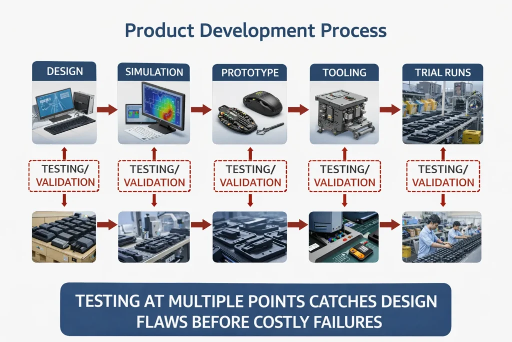
Last but not least, many mold design failures stem from simply not testing enough, or not testing the right things at the right time. We’ve touched on prototyping, but beyond that, there’s the realm of design validation and process validation. Even after the mold is made, the work isn’t over – you must rigorously test that the mold can consistently produce good parts (and that those parts meet all requirements). A significant “gap” occurs when teams rush from T1 (the first trial shots) straight into mass production without sufficient testing, or when they forego simulations and DFM reviews early on.
One critical tool is CAE simulation – for injection molding this often means mold flow analysis (to predict how the plastic fills, where weld lines or air traps might form, whether there will be sink or warp issues). Skipping this analysis in the design phase is asking for trouble. Problems like short shots, or weld lines ending up on a snap fit (creating a weak point), or trapped air causing burns, can often be predicted and solved by tweaking the design or gate locations. Yet, under schedule pressure, some teams skimp on this step. The result? They “discover” these avoidable defects only after the expensive steel mold is made. As noted earlier, fixing a design flaw in CAD might cost a few hours, but fixing it in steel can cost weeks and big dollars. Thus, a robust design process will include early and thorough DFM checks. Many injection molding partners offer a formal DFM review where their engineers go through your part and highlight issues (e.g. “this wall is too thick, that radius is too sharp, this undercut needs a slide, are you sure this material can handle the stress here?”). Such reviews, combined with simulation, act like a “pre-flight checklist,” catching errors that would otherwise emerge as failures in testing or production.
Assuming the design passes those hurdles and you cut the mold, the next potential gap is process validation. It’s not enough that the mold can make one good part; you need to ensure it can make thousands or millions reliably. Process validation is a structured approach (often formal in medtech and aero industries) where you verify the molding process across its expected operating window. For example, you’ll test runs at the high and low ends of the temperature, pressure, and time settings to make sure parts stay within spec. If you skip this and just take the first decent-looking parts as proof everything’s fine, you might get bitten later by variability – perhaps one shift’s production is coming out slightly different because the machine or ambient conditions differ. A famous case involved Philips Healthcare: they received an FDA warning because they hadn’t properly validated the injection molding process for a component, which led to 64 field complaints of failures. In a consumer product like a mouse, stakes aren’t as high as medical devices, but poor process control could still mean high scrap rates or customer returns for intermittent issues (like a button that fails after a month of use due to internal stress, which better molding could have avoided).
Testing gaps also include a lack of real-world trials. It’s one thing to test parts in a lab; it’s another to test them in their actual operating environment. If a gaming mouse is meant to handle millions of clicks, have you life-cycle tested the buttons to see if your design holds up (and that plastic material you chose doesn’t creep or crack)? If the product might be used worldwide, have you done thermal/humidity aging to see if parts warp or become brittle in extreme climates? Sometimes designers rely on material specs or assume testing will be handled later, and those later tests (e.g. beta testing, certification testing) then uncover issues that force a design change or mold modification late in the game. For instance, regulatory tests might show the product fails a drop test because an internal plastic latch snaps – a redesign might call for a metal insert or a thicker rib, which means modifying the mold after it’s built. All of this could be prevented by holistic testing and feedback loops during development.
In summary, no news is not necessarily good news when it comes to design verification. If you haven’t intentionally tested something, assume it’s a risk. The best manufacturers implement multiple feedback loops: design reviews, simulation, prototype/pilot testing, first article inspections, process validations (IQ/OQ/PQ for those in regulated industries), and ongoing monitoring. Each loop is a chance to catch an oversight. The more gaps in this chain, the higher the chance a mold design will “fail” by producing defective parts or requiring late fixes. Conversely, by rigorously testing and validating at each stage, you dramatically improve the odds that your mouse will go from mold to market without nasty surprises. As a testament to this approach, seasoned teams treat injection molding as a partnership between design and production – not a throw-it-over-the-wall transaction. They work closely with tooling engineers, conduct joint reviews, and plan for maintenance and quality checks, thereby closing the gaps where failures sneak through.
Design-for-Manufacturability (DFM) Checklist for Mouse Mold Projects
| Design Aspect | DFM Guideline |
|---|---|
| Wall Thickness | Keep uniform (±10%) to prevent sink marks and stress cracking |
| Draft Angle | ≥1° for polished molds, ≥2–3° for textured surfaces |
| Ribs and Bosses | Use radii and fillets; avoid sharp corners |
| Assembly Fit | Define datum structure, allow for tolerances and assembly gaps |
| Material Shrinkage | Use validated shrink rates; adjust mold cavities accordingly |
| Parting Line & Ejection | Avoid ejector marks on cosmetic zones; plan clean parting lines |
| Gate Location | Avoid weld lines in stress-bearing or visual areas |
| Simulation & Testing | Use Moldflow, test pilot samples, and validate under real conditions |
Conclusion: Designing for Success – Collaboration, DFM, and Continuous Improvement
A recurring theme is the importance of early collaboration and expert input. Engage your mold engineer or manufacturing partner at the design stage to perform a DFM review; this can catch issues like gate locations, wall thickness extremes, or material incompatibilities before they cost you. Similarly, treat your mold maker as a partner rather than a vendor – the best outcomes arise when the toolmaker understands the product’s function and the designer understands the tooling constraints. Many leading companies now conduct joint design reviews, where everyone from industrial designers to quality engineers to toolmakers examine the design for potential failure modes. This holistic approach ensures that by the time the mold is cut, the design is robust. As an EVOK whitepaper put it, injection molding should not be approached as a simple commodity purchase, but as a design-and-manufacturing partnership. That mindset shift alone helps avoid the classic pitfalls.
In practice, avoiding mold design failure means embracing DFM and continuous improvement. Use simulation to predict and eliminate problems like warpage, weld lines, and cooling imbalances. Insist on material analyses to verify your chosen plastic will perform in all expected conditions (and have backup materials qualified in case one doesn’t pan out). Follow established design rules (uniform walls, adequate draft, radiused corners, etc.), but also know when to break them with intent – and only with input from your molder. For instance, if a zero-draft surface is desired for aesthetic reasons, acknowledge it’s a risk and mitigate it (maybe by using a textured mold finish that hides slight ejector marks or by testing a lot). Implement thorough tolerance analysis on assemblies so you know where you need precision and where you can allow a gap or overlap for sanity. And remember that testing is your friend: every prototype or pilot run should be seen not just as a milestone to pass, but as an opportunity to learn and refine the design or process. Each issue uncovered in testing is far cheaper than one found in the field or in a warehouse full of unsellable product.
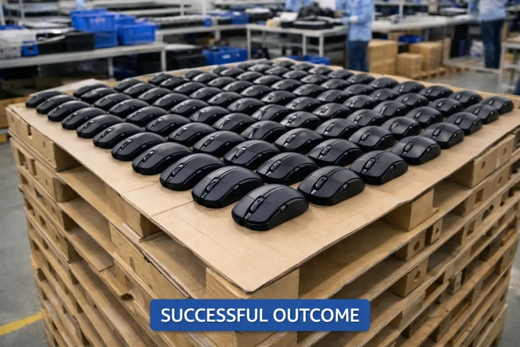
In conclusion, while it’s quoted that “80% of designs fail” initially, this statistic can be turned on its head. With knowledge and preparation, you can be in the 20% that gets it right – or at least catches mistakes early enough to correct course swiftly. The modern toolbox of mold design (digital simulations, advanced materials, precision machining, and a century of collective know-how in plastics) provides everything needed to succeed. By applying the lessons from past failures – be it something as straightforward as adding a degree of draft or as strategic as aligning your team and suppliers’ goals – OEMs and B2B stakeholders can save enormous time and cost, ensuring their next mouse or device goes to production smoothly. At the end of the day, a “failed” mold design is only truly a failure if nothing is learned from it. In the spirit of continuous improvement, every trial, even the failures, make the next design better. Build those learnings into your design process, and you’ll find that you can dramatically lower that 80% figure and hit your product launches with confidence.
Ready to Avoid Mold Design Pitfalls?
At Darshion, we specialize in custom OEM/ODM mouse manufacturing with deep in-house expertise in mold design, tooling, and mass production. Our team has helped hundreds of global brands avoid the most common mold failures—because we’ve seen them all.
Whether you’re prototyping your first ergonomic mouse or optimizing an existing design for mass production, we’re here to support you from concept to finished product.
If you want to reduce risk, improve yield, and work with a trusted mouse manufacturing partner—reach out to us.